
Mars Lander
Play the Mars Lander game here - runs fully in browser
Introduction
Over the Summer of 2018, between part IA and IB of the Cambridge Engineering course, I spent several weeks working on a web-based Martian space simulator. This project was a university assignment, with the task being to complete the position/velocity numerical integration functions, and to try and then land the spacecraft in the game. A secondary task involved programming a basic autopilot using a feedback loop to land the spacecraft. This coursework was (and maybe still is) assigned to Cambridge Engineering students during their Summer vacation between 1st and 2nd years, and introduces numerical methods, control theory, and computer graphics.
The skeleton of some basic code was provided in C++ with OpenGL graphics, but who wants to build a space simulator in pure OpenGL?? This is the era of portable and responsive user applications, and so I decided I’d rebuild this as a web app. Part of why I put so much effort into this was that it was my first proper end-to-end web application, and I was keen to develop these skills as I already was working on FolkFriend at the time. I really enjoyed this project and put a lot of time into it - I was thrilled to recieve the Airbus prize for this submission which was described by the judging professor as “the best in the 10-year history of the competition”.
In this first post I will cover the web-based simulator, graphics, and terrain generation. In the next article we’ll cover how I used a machine learning approach called genetic algorithms to optimise the parameters of the autopilot.
Verlet Integration
The first step was to implement the assigned actual numerical simulation and make sure some plausible physics were the result. We were asked to implement Verlet integration rather than the simpler Euler integration which I had unknowingly used before, to compute the physics update function of the lander. The key difference between Euler and Verlet is that Euler is a first-order method, and Verlet is a second-order method - meaning errors build up much quicker with Euler integration. I was asked not to share the source code on this part since Cambridge Engineering students are pretty handing at copying work from previous year groups…
In any case, implementing the second-order integrator, with a few other bells and whistles like drag in the Martian atmosphere, allows an accurate simulation of the lander dynamics. This is already pretty useful, and the next time you’re in a spacecraft falling through at atmosphere to the ground you might wish you had a Verlet integrator with you to calculate your time until impact. The simulator correctly gives the pre-known correct values that we were assigned to replicate, from set starting positions;
| |
Ouch. If only we could slow down before hitting the surface?
Building Mars
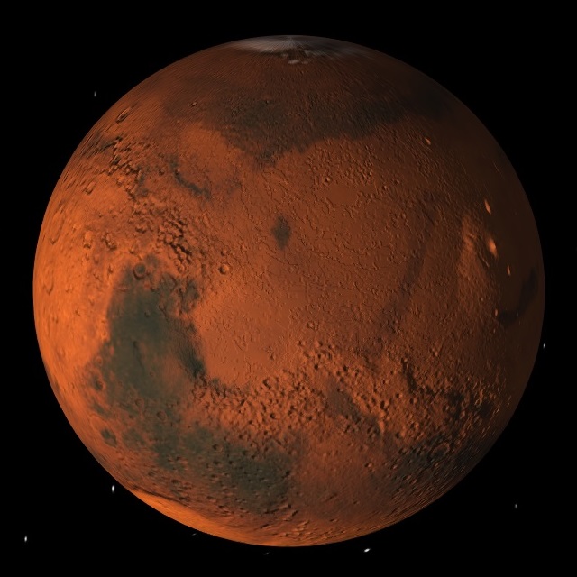
The simulation above works - but there’s no graphics! To build Mars inside a web app, I went for ThreeJS. I’d never done any 3D graphics before, but it wasn’t too difficult to get started with building some cool things right inside the browser. In the assigned C++ code, the lander just starts at a height $h$ above an infinite plane. This doesn’t look very interesting from up in “space”, and so my first step was to add in the planet Mars to my ThreeJS scene. I added a few basic elements: a camera, a simple sphere with a texturemap - courtesy of Planet Pixel Emporium; a light source, and a heightmap to have the surface of the sphere interact nicely with the light. The whole scene is in a large black cube with some stars drawn on. Voila, already we have something looking a lot more Martian.
This looks pretty cool from out in space, but try getting up really close to the surface and this will look pretty weird, because it’s just a PNG on a sphere. There’ll also be precision issues if you’re tens or hundreds of metres away from the surface of an object $7000\text{ km}$ across. So - I needed to design a realistic Martian surface to with the realistic Martian planet.
Terrain Generation
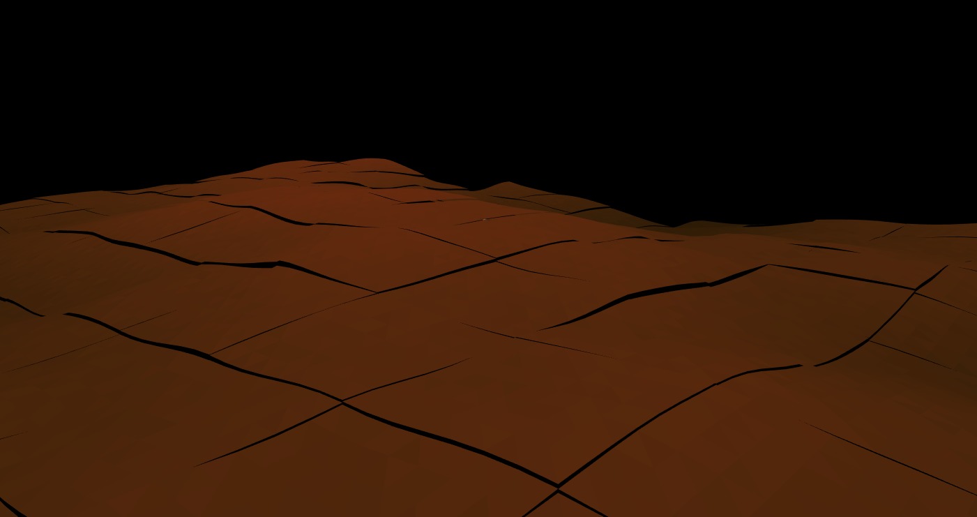
To build a Martian surface, the only practical way is to use a planar mesh, and transition between the sphere to the surface mesh during ascent / descent (some fog shrouds this transition). It took a bit of fiddling to get the angles and camera right so that the surface always feels like it’s pointing “up”, even if it’s upside down relative to where it would be if you landed on the other side of the planet! It’s assumed that the surface is locally flat, that is no amount of travelling laterally will take you to another point of Mars, and if you decide to go up and down a few times you’ll find you always pop back out of the Martian exosphere at the same point you went in!
Developing a realistic terrain involved multiple iterations first with 2D Perlin and then with 2D Simplex noise algorithms, for Martian-like landscapes. Each terrain section, represented by a THREE.PlaneGeometry object, is colored based on altitude with noise, creating a convincing visual.
This worked well, but if the user is travelling fast over the surface they will quickly reach the edge of the generated terrain. We can’t make the terrain mesh too large due to memory constraints, so I aimed to break the terrain into chunks, allowing infinite procedural generation.
2D Simplex Chunks
To ensure there’s always terrain generated directly under the player, I designed a more complex algorithm with two static constants: CHUNK_RENDER_RADIUS and CHUNK_DISCARD_RADIUS. The algorithm calculates the lander’s current chunk, generates and discards chunks based on proximity, and optimizes rendering for a seamless experience.
The steps are as follows:
- Calculate the current chunk based on the lander’s position.
- Identify new chunks to be generated and old ones to be discarded.
- Compute new chunk values using the Simplex algorithm and
THREE.PlaneGeometryvertices.
The size of each chunk reflects a trade-off between CPU and memory - too small and there will the thousands of meshes, too large and each chunk will be cumbersome. I also made use of a web worker to asynchronously compute the chunk meshes ensures smooth terrain generation without affecting the main render thread; I implemented this in respose to frame jitters every time new chunks were being created. The final choice of $ 512\times512\text{ metres}$ reflects the balance between these constraints that provides the best user experience. There is still a visible edge to the terrain, but in the actual game there is some distance fog which shrouds the edge.
Putting this all together, our craft (a spacecraft mesh + texture I found somewhere online) can now travel infinitely over procedurally generated terrain!
Physics and Rendering Synchronization
An improvement from the original C++ OpenGL software is the separation of physics simulation and graphics rendering in the JavaScript implementation. Unlike the original setup, where slowing down the simulation speed also reduced the framerate (and vice versa, speeding it up meant requiring 1000s of frame being rendered per second), the physics engine in the final game ensures independent control.
The main thread framerate and physics update framerate are decoupled, allowing for flexibility based on the user’s device performance. The usual requestAnimationFrame is used in JavaScript to render the graphics scene at a fixed framerate (or as close as the user’s device allows) - this is 60 FPS. The physics thread then follows these steps with each new rendered frame:
- Calculate wall-time difference $\Delta t$ since the last frame (in milliseconds);
- calculate the in-game time passed $t_{\text{game}}$ in that time, using real-timefactor $k_{\text{rtf}}$; $$ t_{\text{game}}=\Delta t \times k_{\text{rtf}}, $$
- calculate and perform $N$ physics updates that occur in $t_{\text{game}}$; $$ N = \frac{{t_\text{game}}}{dt}. $$
This allows the control of three important parameters - render framerate, physics framerate, $dt$, completely independently. This then allows the user to easily speed up or slow down the simulation, meaning they don’t have to wait minutes for a landing from outer space, and can even slow the simulatio right down to try and land more easily. This is achieved simply by scaling the real time factor $k_{\text{rtf}}$. For very high $k_{\text{rtf}}$, the value of $dt$ itself is also increased, so the physics engine doesn’t have to compute hundreds of physics updates per frame. This reduces precision when running very fast, but gives the best in-game experience by keeping the user experience smooth at all time scales.
Bringing It Together
In addition to the improved 3D space view, terrain generation, and physics threading, there were many small tweaks and modifications I added into this project, for general aesthetics and realism.
Cameras, Angles, Quaternions
Getting all the various angles and rotations to work correctly were the hardest part of this entire project. I’d never used 3D graphics before so terms like Euler angles and quaternions were new to me - and proved challenging to get to grips with at first. I made extensive use of three.js’s ability to group meshes together, with a parent-child structure. After a lot of trial and error, I devised the following;
landerGroupis the parent group containing all lander objects, and includes theTHREE.PerspectiveCameraobject that views the scene. When the position of the lander is updated, it islanderGroup.positionthat is changed.- The camera object is in
cameraGroup, which is a child oflanderGroup. When transitioning between surface and terrain mode,cameraGroupis rotated such that the “up” orientation is always the surface normal vector of the sphere. - In space, the
cameraGroupalways takes the same orientation - the up axis is the axis of rotation of Mars (which happens to the y axis, in the scene constructed). - To rotate the lander using the WASD keys, the
landerMeshchild oflanderGroupuses quaternion rotations along with a angular velocity.
Wait, what on Earth (or Mars) is a quaternion? Basically: quaternions are the best way for computers to represent 3D angles and 3D rotation operations.
I’m far from an expert on quaternions, but as an interesting aside, quaternions are effectively a generalisation of complex numbers. The imaginary unit $i=\sqrt{-1}$ is familiar to all engineers and mathematicians, and the orthogonality of real and imaginary numbers presents a natural basis for the space $\cnums$, which I like to think of as a 2D space spanned by the basis vectors $\begin{bmatrix} 1 \\ 0 \end{bmatrix}$, $\begin{bmatrix} 0 \\ i \end{bmatrix}$. By the way, computers don’t actually know about imaginary numbers, being only able to store values 0 or 1, and so generally represent complex numbers with the latter. Quaternions generalise this idea by defining two more imaginary units $j$ and $k$, the famous equations being
$$ i^2 = j^2 = k^2 = -1 = ijk, $$
which is supposed to have struck William Rowan Hamilton in such a flash of genius in 1843 that he immediately stopped and engraved it into a stone on the bridge he was crossing. A key insight is that the above also yields $i=jk$ amongst other results (by careful rearranging of the above and noting the rules like $ij\neq ji$), extending the orthogonality idea to four dimensions. You can watch 3Blue1Brown’s deep dive on this subject if you want some nice visualisations. He sums it up pretty nicely:
Not only do quaternions avoid issues like gimbal lock, they give a really seamless way to interpolate between two 3-Dimensional orientations - one which lacks the ambiguities of Euler angles, and avoids the issues of numerical precision and normalization that arise in trying to interpolate between two rotation matrices.
― 3Blue1Brown
Finishing Touches
- I wrote the exhaust particle trail animation from scratch pretty quickly using some octahedral meshes with randomised opacity, velocity, rotation, colour, but I’m rather pleased with the end result.
- The explosion animation uses essentially the same behaviour but simplified but with some different start and end behaviour, and with velocities generated differently.
- A lightweight 1D Perlin noise implementation is used to generate the random gusts of wind, plus a base magnitudethat is always present.
- Although Mars does graphically rotate, there is no rotation considered in the physics engine.
That covers all the key components of the Mars Lander web game - putting everything here together you can see the game in action below. Why not try it yourself in browser?
In the next article we’ll cover how the lander autopilot works and how I used a machine learning approach called genetic algorithms to optimise the parameters of the autopilot.